

Views: 0 Author: Site Editor Publish Time: 2026-08-21 Origin: Site


High-tonnage marine transfers carry massive operational stakes. Inadequate kinetic energy absorption directly translates to catastrophic hull damage, environmental hazards, and operational downtime. Standardizing collision protection remains difficult across varying vessel displacements, unpredictable sea states, and differing port infrastructures during Ship-to-Ship (STS) and Ship-to-Dock (STD) operations. The Yokohama fender serves as the industry's premier floating marine bumper. It delivers lightweight durability and adaptive energy absorption, making it the most versatile fendering choice for large tankers, container ships, and offshore platforms. The pneumatic Yokohama fender stands as the industry-standard solution for adaptive energy absorption. Successful procurement requires strict adherence to sizing calculations, structural configurations, and ISO 17357 manufacturing standards.

Performance Metrics: Yokohama fenders operate on the principle of air compressibility, offering a non-linear performance curve where energy absorption increases rapidly while reaction force remains relatively low compared to solid rubber fenders.
Compliance is Non-Negotiable: Authentic pneumatic fenders must be manufactured and tested strictly according to ISO 17357-1:2014; non-compliant alternatives introduce severe liability and failure risks.
Configuration Dictates Application: The choice between Chain and Tire Net (CTN) types, Sling types, and ultra-large variants depends entirely on the operational environment, vessel hull sensitivity, and handling capabilities.
Table of Contents
Pneumatic fendering relies entirely on the physics of air compressibility. When a 150,000-ton vessel makes contact with the berth, the internal compressed air displaces the impact energy. This mechanism maintains a low and uniform hull pressure across the entire contact area. Solid rubber alternatives often generate localized stress points. These hard points can easily buckle thin hull plating on modern commercial vessels. A pneumatic unit distributes force evenly, protecting the internal framing of the ship. Angular berthing conditions frequently compromise solid fenders because the impact focuses on a single sharp edge. The pneumatic design adapts to these angles seamlessly. It compresses asymmetrically to absorb the blow. Energy absorption increases rapidly during initial compression. Reaction force remains manageable throughout the deflection cycle. This prevents the ship from bouncing violently off the berth.
Initial internal pressure ratings define operational stiffness. Manufacturers typically supply units rated at 50 kPa or 80 kPa. The 50 kPa models offer softer initial contact. You use these for lighter vessels or highly sensitive hull structures where minimal reaction force is required. The 80 kPa models provide higher energy absorption capacity at 60% deflection. Heavy-duty STS operations generally require the 80 kPa specification to handle massive kinetic loads. Initial pressure directly dictates the resistance encountered during compression. You must match this rating to the specific kinetic energy profile of the berthing vessel. Using an 80 kPa unit on a small, lightweight vessel results in a rigid response. Conversely, a 50 kPa unit on a fully loaded VLCC (Very Large Crude Carrier) might bottom out under heavy swell conditions.
Compression behavior defines the safety limits of the equipment. Maximum compression typically reaches 60% of the original diameter. The internal pressure spikes significantly at this threshold. This tests the tensile strength of the synthetic tire-cord layers. High-quality construction provides a robust safety margin against bursting. These cord layers contain the extreme pressure, acting much like the reinforcement found in commercial aircraft tires. Ultra-large models incorporate a dedicated safety valve located on the end flange. This valve releases excess pressure if compression exceeds safe limits. Accidental over-compression triggers this mechanism instantly. The fender avoids catastrophic rupture by deflating slightly to survive the impact. Vessel safety remains intact even under severe, unexpected impact loads.
Selecting the correct structural configuration ensures operational safety and longevity. Different marine environments demand specific protective features to prevent premature equipment failure.
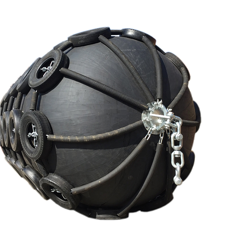
The Chain and Tire Net (CTN) configuration features a robust external network designed for maximum abuse. High-tensile wire or galvanized chain forms the primary web around the pneumatic body. Rubber tires interweave through this network, providing a thick, sacrificial barrier. High-quality units often utilize recycled aircraft tires due to their superior structural integrity. Rubber sleeves cover the chain links entirely to prevent sparking during metal-to-metal contact. This is a mandatory safety feature in oil and gas terminals. This exterior layer absorbs massive abrasive forces before they ever reach the pressurized hull.
CTN remains the default choice for heavy-duty STS operations. Rough-weather STD berthing also demands this level of protection. The net shields the main pneumatic body from sharp protrusions. Quay walls often harbor hidden debris, exposed rebar, or jagged concrete edges. The tires take the brunt of this physical damage. The inner pressure vessel remains uncompromised, maintaining its airtight seal. Port authorities heavily favor CTN variants for common-use berths where vessel types and crew skill levels vary wildly.
This configuration introduces specific operational trade-offs. The chain net adds significant weight to the overall unit. Handling requires heavier lifting gear, robust deck cranes, and specialized rigging. Abrasive wear poses a risk to highly sensitive hull coatings. The continuous rubbing of the tires against the ship can strip specialized anti-fouling paints. Naval vessels often avoid CTN units for this reason, preferring smoother alternatives. Specialized LNG carriers also require careful consideration before deploying netted variants, as hull friction must be minimized.
Sling-type fenders utilize a bare pneumatic cylinder design. They lack the external tire network entirely. Reinforced lifting eyes attach directly to each end of the unit. Heavy-duty galvanized steel flanges secure these lifting points to the rubber body. The exterior relies entirely on a thickened outer rubber layer for protection against the elements and physical impact. This outer layer is specially compounded to resist tearing and gouging.
Applications requiring rapid deployment heavily favor the sling type. Their lighter weight simplifies handling procedures significantly. Smaller deck cranes or even manual winches can maneuver them easily into position. Operations involving vessels with sensitive hull paints benefit greatly from this design. The smooth outer rubber prevents scratches and coating degradation during the constant rise and fall of the tides. Passenger ferries, luxury yachts, and naval ships frequently utilize this configuration to maintain pristine hull aesthetics.
Puncture resistance drops noticeably compared to CTN models. Sharp quay edges pose a severe threat to the bare rubber. Protruding bolts or broken timber pilings can easily breach the outer layer. You must conduct more frequent outer-rubber inspections to identify potential weak points. Any deep gouge compromises the structural integrity and increases the risk of a blowout under pressure. Sling types require cleaner, well-maintained berthing environments to function safely over an extended lifecycle.
Offshore energy sectors deploy ultra-large Yokohama fender models to manage extreme kinetic forces. These oversized units increase safety during volatile offloading procedures in open water. LNG-FPSO (Floating Production Storage and Offloading) and LNG tanker transfers require massive energy absorption capabilities. Ultra-large fenders enable vessels to maintain a significantly greater stand-off distance. This distance prevents superstructure collisions during heavy sea swells, where vessels roll heavily toward one another. Diameters often exceed 3.3 meters, and lengths can surpass 10 meters, providing a massive buffer zone.
Modified pneumatic fenders serve highly specialized marine functions beyond simple berthing. The Globuoy represents a prime example of this adaptation. Engineers modify pneumatic technology for use as surface or sub-sea buoys. These units facilitate heavy equipment installation by providing adjustable buoyancy. Offshore mooring operations rely on their immense lifting capacity to support heavy chains and anchors. Deep-water anchoring systems utilize them to keep mooring lines taut. The internal pressure adapts to varying water depths, making them incredibly versatile tools for subsea engineering projects.
Accurate sizing prevents catastrophic equipment failure. Guesswork has no place in marine engineering, especially when dealing with thousands of tons of moving steel.
Calculating berthing energy forms the absolute foundation of fender selection. The kinetic energy formula incorporates vessel displacement tonnage as the primary mass variable. Approach velocity acts as the most significant factor in this equation. Velocity squares within the calculation, amplifying its impact exponentially. A ship moving at 0.2 meters per second generates vastly less energy than one moving at 0.3 meters per second. The added mass coefficient accounts for the volume of water moving alongside the hull, which pushes the ship forward even after engines reverse. Eccentricity factors adjust for the angle of impact, as ships rarely berth perfectly parallel. Berthing configuration dictates the final energy profile that the fender must absorb.
To properly size a pneumatic fender system, marine engineers follow a strict sequence of calculations:
Determine the maximum displacement tonnage of the largest vessel expected at the berth.
Establish the maximum allowable approach velocity based on local port regulations and tugboat availability.
Calculate the normal kinetic energy using the standard berthing formula, factoring in the added mass of the surrounding water.
Apply the eccentricity coefficient based on the anticipated angle of approach and the vessel's center of gravity.
Identify the maximum allowable hull pressure for the specific vessel class to ensure the fender's reaction force does not cause structural yielding.
Select a fender diameter and length that provides the required energy absorption at 60% deflection while staying below the hull pressure limit.
Clearance requirements dictate the physical dimensions of the fender. You must determine the necessary stand-off distance before selecting a diameter. STS transfers require sufficient space between hulls to prevent bridge wings or antennas from interlocking. STD operations need clearance between the vessel's flared bow and the quay cranes. Superstructure collision remains a constant threat during rolling and pitching in open water. Deep-draft vessels exhibit significant angular movement during loading and unloading. Ultra-large fenders mitigate these collision risks in volatile offshore operations. The fender diameter must always exceed the maximum anticipated roll angle intrusion.
Hull pressure limitations restrict the allowable reaction force generated by the fender. The fender's contact area must distribute the load safely across the ship's internal framing. You match the reaction force to the allowable hull pressure of the berthing vessels. Thin-hulled tankers possess strict pressure thresholds that cannot be exceeded without causing permanent indentations. Container ships feature specific reinforced frame locations, requiring precise fender placement. Offshore platforms require customized pressure distribution to protect their tubular steel jackets. Exceeding these limits causes permanent hull deformation, leading to immediate classification society interventions. The pneumatic design excels here by expanding the contact area dynamically as it compresses.
Environmental factors heavily influence the required fender specifications. Wave height alters the vertical movement of the vessel, requiring longer fenders to ensure continuous contact. Tidal variations shift the contact point along the quay wall, demanding vertical adaptability. Wind loads push the vessel continuously against the berth, requiring sustained energy absorption capabilities without bottoming out. Strong currents alter the approach velocity unexpectedly, forcing the fender to absorb sudden kinetic spikes. You must calculate these environmental extremes before finalizing the fender diameter and length.
Performance Parameter | 50 kPa Initial Pressure | 80 kPa Initial Pressure |
|---|---|---|
Energy Absorption Capacity | Standard Baseline | High (Approx. 20-30% greater) |
Reaction Force | Lower / Softer | Higher / Firmer |
Hull Pressure Distribution | Extremely Soft | Firm but Uniform |
Primary Application | Sensitive Hulls, Light Vessels | Heavy-Duty STS, Large Tankers |
Deflection at Max Load | Reaches 60% faster | Resists compression longer |
Procuring marine safety equipment demands rigorous vendor vetting. ISO 17357-1:2014 serves as the absolute baseline for quality, safety, and reliable performance.
Material specifications dictate long-term durability in harsh marine environments. A compliant Yokohama fender consists of three distinct, highly engineered layers. The inner rubber layer guarantees absolute airtightness. It prevents pressure loss under extreme deformation and constant flexing. The synthetic-tire-cord layer acts as the primary pressure retention structure. It distributes the stress of the internal compressed air evenly across the entire cylinder. The outer rubber layer provides necessary abrasion and weather resistance. It must withstand intense UV radiation, continuous saltwater exposure, and physical scraping against concrete quays. If any of these three layers utilize substandard materials, the entire unit becomes a liability.
Mandatory testing protocols validate the engineering design and manufacturing process. Vendors must provide comprehensive documentation for every unit produced. Material physical property tests confirm rubber tensile strength and elongation both before and after artificial aging. Dimensional inspections verify exact sizing under standard initial pressure, ensuring the unit fits the intended operational space. Air-leakage tests ensure the inner rubber maintains integrity over extended periods. This typically requires the fender to hold pressure for 30 minutes without a measurable drop. Performance tests measure the exact deflection under specific loads. Manufacturers must compress the fender to 60% using a massive hydraulic press and record the precise energy absorption and reaction force curves.
Identifying substandard products prevents catastrophic operational failures. Counterfeit or poorly manufactured fenders frequently flood the maritime market, offering dangerous shortcuts. Lack of third-party classification society certificates serves as an immediate red flag. Reputable vendors supply verifiable certificates from ABS, DNV, or LR for each individual fender. Missing safety valves on fenders larger than 2.5m diameter indicates severe non-compliance with ISO standards. Uneven outer rubber thickness suggests poor vulcanization processes, leading to premature delamination. Inferior synthetic-tire-cord layers lead to sudden, explosive bursting under load. You must demand full traceability of materials, testing data, and factory audit reports before authorizing any purchase.
Even the highest quality equipment fails if deployed incorrectly. Operational protocols must match the rigorous engineering standards of the fenders themselves.
Deployment and mooring failures introduce immediate hazards to the vessel and crew. Incorrect towing angles place immense, localized stress on the end flanges. Towing lines must remain parallel to the fender's longitudinal axis to prevent tearing the flange from the rubber body. Improper shackle sizing leads to sudden hardware failure under load, turning heavy metal components into dangerous projectiles. Using wire ropes directly on fender lifting eyes causes rapid metal fatigue and cuts into the rubber. You must use proper swivels and guy ropes during installation. Swivels prevent the mooring lines from twisting, binding, and eventually snapping. Guy ropes stabilize the unit during positioning, preventing it from swinging violently in high winds.
Over- and under-pressurization compromise the entire fendering system. Failing to maintain the specified initial internal pressure creates severe operational hazards. Under-inflated units suffer from drastically reduced energy absorption capacity. The vessel hull may strike the quay wall straight through the collapsed fender, causing massive structural damage. Over-inflated units exhibit an increased reaction force, acting more like a solid wall than a cushion. The hull experiences higher stress than anticipated, potentially buckling internal frames. Over-inflation also elevates the burst risk during maximum compression, as the safety valve may not vent fast enough to handle the pressure spike. You must calibrate pressure gauges regularly and adjust internal air levels based on ambient temperature fluctuations.
A routine maintenance schedule ensures long-term reliability and protects the initial investment. Regular, documented maintenance extends the operational lifecycle significantly, ensuring the fenders perform flawlessly when needed most. Field crews should execute the following maintenance protocol:
Conduct daily visual inspections to identify new abrasions, cuts, or chain net damage before they escalate into structural failures.
Inspect the outer rubber for deep cuts exposing the synthetic-tire-cord layer; any exposed cord requires immediate vulcanized repair.
Perform monthly pressure gauge readings to confirm airtightness and operational readiness, investigating any unexpected pressure drops immediately.
Replace safety valves periodically to maintain burst protection, as saltwater corrosion can seize the internal springs over time.
Swap out chain nets when wire links show significant corrosion or when the sacrificial tires wear down to their own internal cords.
Compile your exact vessel displacement data, maximum approach velocities, and specific port environmental conditions into a standardized technical brief.
Measure the required stand-off distance to prevent superstructure interference during maximum anticipated roll angles at your specific berth.
Request a formal technical sizing calculation and quote from a fully certified pneumatic fender manufacturer, demanding verifiable ISO 17357 documentation.
Establish a clear deployment, inflation, and maintenance protocol for your deck crew prior to equipment delivery to ensure immediate operational readiness.
For marine operators seeking dependable fendering solutions, Hongruntong Marine provides marine fender products and technical support for demanding berthing and offshore applications. With a focus on product quality, practical engineering requirements, and marine operational needs, the company supports customers in selecting suitable fender solutions for safer and more reliable vessel operations.
A: A Yokohama fender is a floating marine bumper that uses compressed air to absorb impact energy. "Yokohama" is the original manufacturer name that became the generic industry term for high-pressure floating pneumatic fenders used in heavy-duty marine operations.
A: A high-quality pneumatic fender typically lasts 10 to 15 years. This lifespan is contingent on minimizing severe UV exposure, adhering to strict maintenance schedules, maintaining correct internal pressure, and avoiding catastrophic puncture events from sharp quay structures.
A: The safety valve releases excess internal pressure during extreme compression events. This safety mechanism prevents the fender from bursting if the impact energy drastically exceeds the designed operational limits, ensuring the structural integrity of the unit.
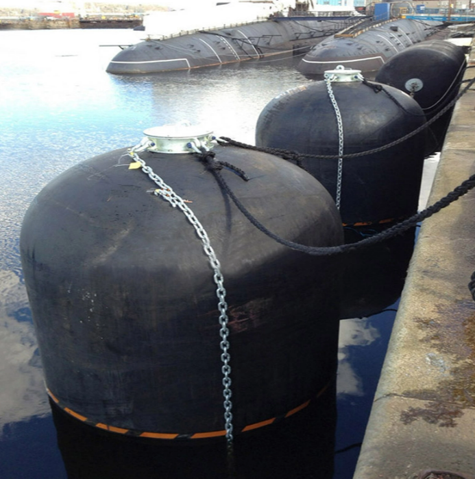
A: Standard pneumatic fenders float horizontally and are not ideal for submarines. However, hydro-pneumatic fenders are a vertically floating variant specifically designed for sub-surface hull contact, making them perfect for submarine berthing operations.
A: Operators check the internal pressure using a specialized pressure gauge assembly. This gauge connects directly to the end flange valve. Regular monthly checks ensure the pressure matches the initial 50 kPa or 80 kPa rating.
A: ISO 17357 certification guarantees the fender's performance metrics under maximum load. It ensures strict material quality and testing protocols. Lack of certification introduces severe liability risks, invalidates insurance coverage, and increases the probability of catastrophic failure.


