

Views: 0 Author: Site Editor Publish Time: 2026-08-21 Origin: Site


Marine berthing and Ship-to-Ship (STS) transfers generate massive kinetic energy. When a 100,000-ton vessel approaches a quay, the momentum requires immediate management to prevent hull deformation or dock damage. Specifying inadequate fender systems leads to accelerated wear, sudden structural failures, extended port downtime, and severe safety hazards. Industry professionals often use the term "Yokohama fenders" interchangeably with this technology because Yokohama pioneered the design. However, technical evaluations and procurement protocols must focus on the generic classification: Pneumatic Fenders. Evaluating these systems requires looking past brand names to verify adherence to universal manufacturing standards. These units serve as the industry standard for dynamic energy absorption. They handle extreme loads by utilizing compressible air rather than relying solely on the elasticity of solid rubber. Understanding their internal mechanics, pressure ratings, and multi-layered structural integrity ensures accurate technical evaluation and safe deployment in harsh marine environments.

Energy Absorption Mechanism: Pneumatic fenders utilize the compressibility of air to absorb kinetic energy, offering low reaction force even under high deflection to protect both the ship and the dock.
Structural Integrity: Performance relies on a strict three-tier construction—outer rubber, synthetic-tire-cord, and inner rubber—dictated by ISO 17357 standards.
Pressure Specifications: Proper specification requires choosing between standard initial internal pressures (typically 50 kPa or 80 kPa) based on vessel displacement and berthing velocity, as pressure directly controls energy absorption capacity.
Compliance is Critical: Procurement must demand documented ISO 17357-1:2014 compliance to ensure verifiable performance curves and safety under maximum load.
Table of Contents
The fundamental principle driving these systems is the compressibility of gases. As a vessel makes contact and compresses the fender body, the internal volume of the air chamber decreases. According to basic gas laws, this reduction in volume causes the internal air pressure to rise proportionally. The trapped air acts as a highly responsive, heavy-duty shock absorber.
This rising internal pressure cushions the impact. It actively dissipates the vessel's kinetic energy before that energy transfers into the rigid dock structure or the adjacent ship's hull. The air effectively pushes back against the vessel, decelerating it smoothly over a distance of several feet depending on the cylinder's diameter. You see this in action during STS transfers between a Very Large Crude Carrier (VLCC) and an Aframax vessel. The air volume absorbs the rolling motion of both ships simultaneously.
Contrast this air compression mechanism with solid rubber fenders. Solid rubber relies entirely on material deformation to absorb energy. Solid systems become stiffer as they compress, transferring higher forces directly to the hull plating. Pneumatic systems offer superior adaptability. They conform to varying impact angles, adjust instantly to tidal fluctuations, and maintain consistent performance during continuous wave motion. The air inside distributes the load evenly across a massive surface area, preventing localized pressure points that cause structural yielding.
Evaluating performance requires analyzing two specific metrics: Reaction Force and Energy Absorption. Reaction Force is the physical pushback exerted against the vessel hull during compression. Energy Absorption is the total amount of kinetic energy the unit successfully neutralizes. You want maximum energy absorption with the lowest possible reaction force.
The performance curve of a pneumatic system remains unique in marine engineering. These units maintain a relatively low and highly stable reaction force up to a 60% deflection rate. This soft initial response protects thin-skinned vessels like LNG carriers or naval frigates, which cannot withstand high point loads without suffering permanent hull deformation. The air compresses smoothly, keeping the pushback manageable while still absorbing massive amounts of energy.
During the procurement phase, you must evaluate manufacturer performance curves meticulously. Verify that the guaranteed energy absorption meets your maximum berthing velocity calculations. You must also ensure the corresponding reaction force remains well below the allowable hull pressure limits of the vessels frequenting your facility. Reject any performance curves showing sharp spikes in reaction force at lower deflection percentages.
Deflection Percentage | Solid Rubber Reaction Force Profile | Pneumatic Reaction Force Profile |
|---|---|---|
10% to 20% | Rapid increase, stiff initial contact | Soft contact, slow pressure build-up |
30% to 40% | High pushback, transfers shock to hull | Stable pushback, high energy absorption |
50% to 60% | Maximum stiffness, potential hull damage | Controlled peak force, safe deceleration |
The outer rubber layer serves as the first line of defense against a hostile marine environment. Manufacturers engineer this compound specifically to withstand severe abrasion against rough concrete quays and barnacle-encrusted steel hulls. It must resist tearing and shear forces generated when a vessel slides along the berth during mooring operations.
Beyond physical impacts, the outer rubber endures harsh weather conditions. It contains specialized carbon black additives to resist ultraviolet (UV) degradation, ozone cracking, and continuous exposure to corrosive saltwater. The thickness of this layer is strictly regulated by international standards. It must be thick enough to protect the internal structural cords from deep punctures, cutting debris, and long-term environmental degradation. If the outer rubber fails, the internal structural integrity immediately degrades.

The synthetic-tire-cord layer functions as the structural skeleton. Without this layer, the pressurized air would simply balloon and rupture the rubber casing. Manufacturers use high-tensile synthetic cords, typically nylon or polyester, similar to those found in heavy-duty aircraft or mining tires. These provide the necessary burst resistance.
These cords are arranged at optimal bias angles. This cross-ply arrangement distributes the impact load evenly across the entire surface of the cylinder. It provides the tensile strength required to contain the high-pressure internal air during maximum compression events. The engineering here is precise; the angle of the cords dictates how the cylinder changes shape under load without bulging irregularly.
When evaluating these systems, the number of cord layers serves as a primary dimension of quality. The layer count directly correlates to the pressure rating, overall burst resistance, and long-term durability. A unit designed for an 80 kPa initial pressure requires significantly more synthetic-tire-cord layers than a 50 kPa unit to maintain the same safety factor under maximum deflection.
The inner rubber layer has a singular function: it acts as a highly impermeable membrane designed to seal the pressurized air inside the chamber. While the outer layers handle mechanical stress, the inner layer ensures gas retention. It utilizes butyl rubber compounds to remain flexible enough to fold and compress without cracking.
Manufacturing this layer involves strict quality control. Any impurity in the rubber compound or flaw in the vulcanization process leads to micro-leaks. Over the operational lifespan, micro-leaks cause the internal pressure to drop gradually, severely reducing the energy absorption capacity. High-quality inner layers maintain pressure for months, minimizing the need for constant maintenance and reinflation by the deck crew.
The ends of the cylinder feature metallic flange openings that house the valve systems. These components are constructed from hot-dipped galvanized steel or stainless steel to prevent saltwater corrosion. For any unit over 2.5 meters in diameter, international standards mandate the inclusion of a specialized safety valve alongside the standard air inflation valve.
The air inflation valve allows crews to conduct routine pressure checks and top up the air using standard heavy-duty compressors. The safety valve acts as a fail-safe. During extreme, unforeseen compression events—such as a vessel approaching too fast—the internal pressure can spike beyond the burst limit of the synthetic cords. The safety valve automatically vents excess pressure, preventing a catastrophic explosion of the rubber body.
Field maintenance for these valves requires specific steps:
Inspect the flange bolts monthly for signs of rust or galvanic corrosion.
Verify the torque specifications on all flange bolts using a calibrated torque wrench.
Remove salt buildup from the air inflation valve threads using a wire brush and marine-grade lubricant.
Test the safety relief valve annually by applying controlled over-pressure to ensure it vents at the exact specified threshold.
Initial Internal Pressure (Pi) is the baseline pressure of the unit when it is fully inflated but completely uncompressed. It serves as the starting point for all performance calculations. The maritime industry relies on two primary standard ratings: Pneumatic 50 (P50) and Pneumatic 80 (P80).
P50 indicates an initial internal pressure of 50 kPa (approximately 0.5 kgf/cm²). P80 indicates an initial internal pressure of 80 kPa (approximately 0.8 kgf/cm²). This initial pressure acts as the primary control mechanism for the system. It dictates the baseline stiffness of the cylinder and establishes the total energy absorption capacity available before the unit bottoms out.
End-Pressure refers to the internal air pressure recorded when the unit reaches its maximum designed deflection, which is typically 60% of its original diameter. As the volume shrinks by 60%, the internal pressure rises dramatically. The synthetic tire cords must contain this end-pressure without yielding or snapping.
Manufacturers build significant safety margins into these pressure ratings. A high-quality unit undergoes hydrostatic testing to withstand pressures well beyond the 60% deflection end-pressure. This prevents bursting under maximum allowable compression. However, pushing the system past 60% deflection rapidly degrades the safety margin and risks structural failure.
Choosing between P50 and P80 requires a strict decision framework based on operational data. You must analyze the vessel deadweight tonnage (DWT), the maximum expected approach velocity, the berthing angle, and the specific application.
Higher pressure (P80) offers significantly greater energy absorption within the exact same physical footprint. This makes P80 ideal for tight berths or when handling larger vessels without upgrading the physical size of the mooring infrastructure. However, P80 units exert a slightly higher initial reaction force against the hull. If you accommodate older vessels with weakened hull plating, a larger P50 unit provides the necessary energy absorption with a gentler initial pushback.
Vessel DWT (Approximate) | Recommended Fender Size (Diameter x Length) | Typical Pressure Rating |
|---|---|---|
Up to 10,000 DWT | 1.5m x 3.0m | P50 |
10,000 to 50,000 DWT | 2.0m x 3.5m | P50 or P80 |
50,000 to 100,000 DWT | 2.5m x 5.5m | P80 |
Over 100,000 DWT (VLCC) | 3.3m x 6.5m or 4.5m x 9.0m | P80 |
ISO 17357-1:2014 is the absolute, non-negotiable benchmark for high-pressure floating pneumatic rubber fenders. Procurement teams must reject any product that cannot provide documented proof of this specific certification. This standard separates engineered safety equipment from dangerous, substandard imitations.
The certification guarantees rigorous testing protocols. It mandates specific material testing for the rubber compounds, strict dimensional tolerances, and verified performance testing for both energy absorption and reaction force. It requires parallel compression tests and angular compression tests to simulate real-world berthing. Warn your procurement department against suppliers claiming their products are "ISO-equivalent" or "built to ISO standards" without providing official, third-party verification certificates from recognized classification societies like ABS, LR, or DNV.
Selecting the right external configuration is just as important as selecting the right internal pressure. The operational environment dictates this choice.
Chain Tire Net (CTN) Type: This configuration features a heavy-duty chain net fitted with rubber sleeves and used aircraft or truck tires. The net wraps entirely around the rubber body. It handles heavy-duty applications, STS transfers, and high-abrasion environments. The tires absorb the friction and cutting forces of the ship's hull, protecting the main pressure vessel. When the tires wear out, you replace the net, extending the life of the core unit.
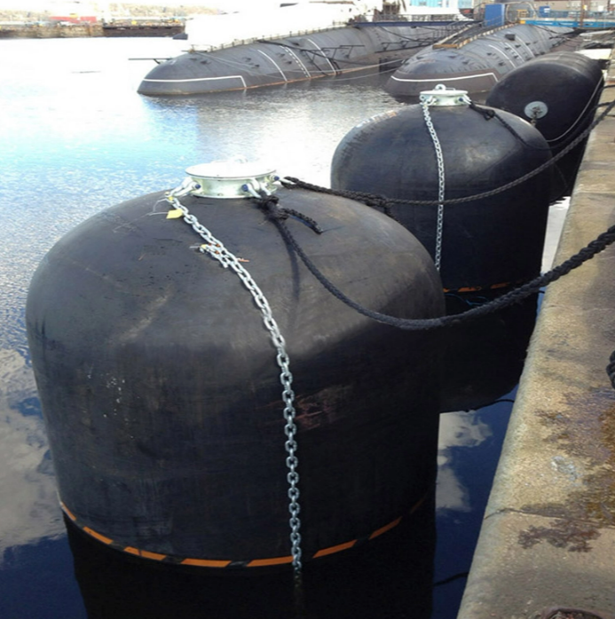
Sling Type: This is the bare fender configuration. It features reinforced attachment eyes directly at each end but lacks the external chain and tire net. Sling types fit lighter vessels, specific naval applications, or operations where minimizing the overall lifting weight is a priority. They are easier to handle but expose the outer rubber layer directly to hull friction.
Deploying these systems safely requires specific rigging hardware. You cannot simply tie them off with standard synthetic mooring lines. Critical setup components include high-tensile wire ropes or chains, heavy-duty towing rings, and certified shackles. Most importantly, you must install swivels at both ends of the mooring assembly. Swivels prevent the guy chains from twisting, binding, and snapping as the cylinder rolls with the movement of the ship.
Rigging requirements differ significantly based on the operation. Ship-to-Dock (STD) installations require complex tidal adjustment considerations. The mooring chains must allow the unit to float up and down the quay wall without hanging up on dock structures or getting pinned under the pier at high tide. Ship-to-Ship (STS) floating deployments require rigging that keeps the units properly spaced along the hull, often utilizing a continuous wire rope setup to maintain alignment in open water.
Maintaining the exact specified internal pressure is the most critical operational requirement. Deviating from the manufacturer's pressure chart leads to immediate performance failures.
Under-pressurization is highly destructive. A soft unit allows excessive deflection. The vessel will push the cylinder past the 60% limit, causing it to bottom out. When this happens, the inner layers crush against each other, snapping the synthetic tire cords and completely voiding the energy absorption capabilities. The ship will then impact the dock.
Over-pressurization is equally dangerous. Pumping too much air into the chamber increases the baseline stiffness. This drastically increases the reaction force beyond safe limits, transferring shockwaves directly into the vessel hull. It pushes the synthetic cords closer to their burst limit before the ship even makes contact. You mitigate these risks through strict adherence to manufacturer inflation charts and by taking temperature-adjusted pressure readings. Internal pressure fluctuates with ambient weather; a unit inflated in the cool morning will experience a pressure spike under the hot afternoon sun.
Operating in debris-heavy ports or alongside vessels with hull protrusions presents constant puncture risks. While the outer rubber is tough, sharp steel under immense pressure will slice through it.
For CTN configurations, you must inspect the net regularly. Ensure the tires cover the main body adequately and that no broken chain links dig into the rubber. If a chain snaps, the jagged edge acts like a knife against the pressurized cylinder. Replace worn tires and rusted shackles immediately to ensure the net continues to protect the main body.
Implementing a realistic and strict maintenance schedule prevents catastrophic failures during berthing operations. Follow these baseline protocols:
Conduct monthly visual inspections to identify deep abrasions, cuts in the outer rubber, or degradation in the chain tire net.
Perform quarterly internal pressure checks using calibrated, liquid-filled pressure gauges to ensure accuracy.
Adjust internal pressure seasonally to account for ambient temperature changes affecting gas expansion.
Execute annual inspections of all metallic components, including safety valves, towing rings, and flange hardware, checking for severe corrosion or metal fatigue.
Test the safety relief valve annually to ensure it opens at the correct over-pressure threshold.
To move forward safely and effectively with your marine procurement and deployment, take the following actions:
Calculate your maximum kinetic energy requirements based on the heaviest vessel and highest approach velocity expected at your facility.
Request and independently verify certified performance curves from potential suppliers to ensure reaction forces remain within safe hull limits.
Consult manufacturer load tables to match your energy requirements with the exact diameter and pressure rating needed.
Audit the testing facilities and ISO 17357 certificates of potential suppliers before finalizing any procurement contracts.
Establish a strict, documented maintenance schedule for your deck crew to monitor internal pressure and inspect rigging hardware monthly.
For marine operators seeking dependable fender solutions, Hongruntong Marine provides marine fender products and solutions for demanding berthing and Ship-to-Ship applications. With a focus on product quality, marine application requirements, and reliable performance, the company supports ports, terminals, shipyards, and vessel operators in selecting suitable fender systems for safer and more efficient marine operations.
A: The maritime industry primarily uses two standard initial internal pressures: 50 kPa (P50) and 80 kPa (P80). The choice depends on the required energy absorption and the allowable reaction force for the specific vessels using the berth.
A: You check the pressure using a calibrated gauge attached to the air inflation valve located on the end flange. To adjust, you either release air through the valve or connect a standard heavy-duty air compressor to top it up to the manufacturer's specified baseline.
A: "Yokohama" is a brand name that pioneered the technology, leading to it becoming a genericized trademark in the industry. "Pneumatic fenders" is the correct technical and generic term for any floating rubber fender that uses compressed air to absorb impact.
A: High-quality units manufactured to ISO 17357 standards typically last between 10 to 15 years. Lifespan depends heavily on the operational environment, the frequency of use, and strict adherence to routine maintenance and pressure-check protocols.
A: Over-inflation makes the unit too stiff. This drastically increases the reaction force, which can damage the ship's hull plating upon impact. It also stresses the internal synthetic tire cords, increasing the risk of a catastrophic blowout under heavy compression.
A: Yes, they are the global standard for STS transfers. Their ability to float, adapt to wave motion, and maintain a safe standoff distance makes them ideal. Chain Tire Net (CTN) configurations are usually preferred for STS to handle the high friction between two moving vessels.
A: ISO 17357 is the strict international standard dictating material quality, structural design, and performance testing. Certification guarantees the unit will absorb the stated kinetic energy safely without bursting, ensuring the protection of the vessel, the crew, and the port infrastructure.


