

Views: 0 Author: Site Editor Publish Time: 2026-08-21 Origin: Site


Marine berthing, Ship-to-Ship (STS) transfers, and terminal operations operate under high-stakes realities where kinetic energy management dictates vessel safety and infrastructure integrity. Specifying the wrong floating fender system introduces severe operational risks. You might face catastrophic hull damage, compromised LNG transfers, or excessive maintenance downtime. Premature replacement cycles disrupt critical port schedules and strain maintenance resources. An objective, engineering-based comparison between the two dominant floating fender technologies is necessary. We must evaluate pneumatic (Yokohama-type) and foam-filled fenders. This article assesses both systems across performance metrics, operational realities, and specific marine applications. You will learn how to match the right technology to your specific port or vessel requirements. This ensures safe, reliable, and continuous marine operations under demanding conditions.
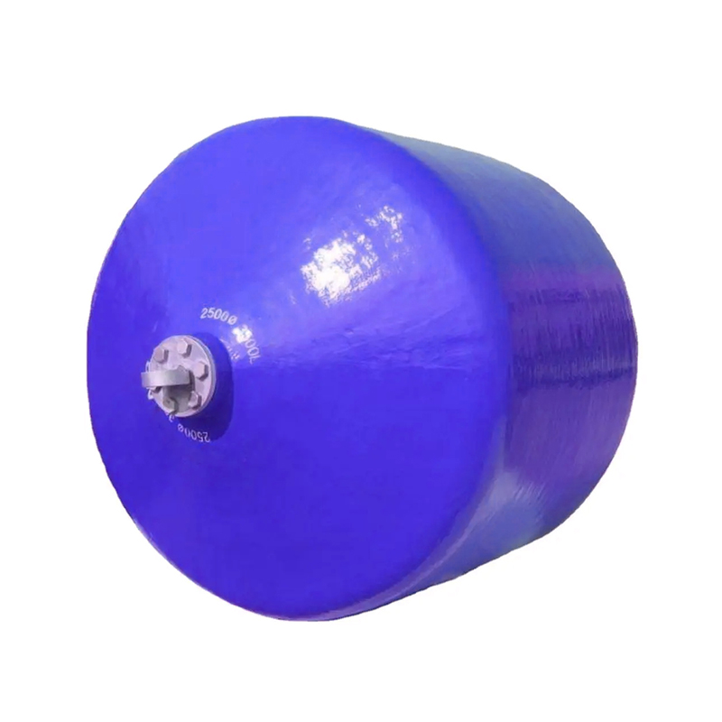
Operational Mechanism: Pneumatic fenders utilize compressible air to absorb impact, offering dynamic flexibility and even pressure distribution, while foam fenders rely on a closed-cell foam core that compresses to dissipate kinetic energy without the risk of deflation.
Testing and Compliance: Pneumatic systems benefit from the globally recognized ISO 17357 testing standard, ensuring predictable performance baselines. Foam fenders lack a universal ISO standard, relying instead on stringent, manufacturer-specific testing protocols.
Logistics and Maintenance: Pneumatic fenders can be deflated for highly efficient transport and storage but require routine maintenance of safety and ball valves. Foam fenders demand minimal maintenance due to the absence of end fittings but require more logistical planning for transport due to their rigid volume and heavier weight.
Application Specificity: The choice between pneumatic vs foam fenders ultimately depends on hull pressure limits, tidal variations, puncture risk profiles, customization needs, and whether the application is STS, LNG, or fixed-port berthing.
Table of Contents
Establish the baseline success criteria for any marine fender system. You must maximize kinetic energy absorption. Simultaneously, you must minimize the reaction force exerted against the vessel hull and the berthing structure. Achieving this balance prevents structural fatigue and catastrophic hull breaches during complex berthing maneuvers. The approach velocity, displacement tonnage, and berthing angle of the vessel dictate the massive kinetic loads the fender must absorb.
Pressurized air serves as a highly efficient energy-absorbing medium. Pneumatic fenders leverage this principle to manage massive kinetic loads. The construction relies on three primary layers engineered to handle extreme stress. The inner rubber layer seals the pressurized air, maintaining the required internal pressure over long operational periods. The synthetic-tire-cord layer provides the structural reinforcement necessary to withstand immense internal pressure spikes during compression. The outer rubber layer protects the fender from abrasion, ozone degradation, and severe environmental weathering.
Upon impact, the internal air volume compresses. This compression absorbs the kinetic energy of the approaching vessel. The internal pressure expands and distributes the load evenly across the contact area. This dynamic provides progressive shock absorption. It also offers exceptional flexibility, allowing the fender to conform to various hull profiles without creating dangerous pressure points. Standard internal pressures typically sit at 50 kPa (P50) or 80 kPa (P80), allowing port engineers to select the appropriate baseline stiffness for their specific traffic.
Foam-filled fenders utilize elastomeric foam compression to manage impact energy. The core consists of closed-cell polyethylene foam. This core is encapsulated within a reinforced polyurethane elastomer skin. Manufacturers often use filament winding techniques to reinforce this outer skin. They wrap continuous synthetic fibers around the foam core while applying liquid polyurethane. This creates a matrix that resists tearing even under heavy shear loads.
The fundamental structural difference lies in the absence of internal air pressure. The closed-cell foam compresses to dissipate kinetic energy through mechanical deformation. Because the cells are independent and closed, water cannot migrate through the core. The fender maintains its form, rigidity, and basic function even if the outer skin is severely breached. This solid-state mechanics eliminates the risk of sudden deflation, ensuring continuous protection in hazardous environments.
When analyzing Pneumatic vs Foam Fenders, you must evaluate specific performance metrics. These dimensions dictate how each system handles real-world berthing forces and operational abuse.
Compare the energy distribution curves of both systems. Pneumatic fenders maintain exceptionally low reaction forces even under high-compression angles. They offer superior versatility by conforming seamlessly to varying hull shapes. This conformity distributes pressure evenly across a much wider contact area. Vessels with sensitive hull structures, such as LNG carriers or naval frigates, benefit greatly from this even pressure distribution. The soft initial reaction force gradually increases as the air compresses, preventing sudden jolts to the vessel.
Foam fenders exhibit linear or non-linear reaction force profiles. This depends entirely on the specific foam density chosen during manufacturing. Higher density foam absorbs more energy but generates a higher reaction force. They present a more rigid contact footprint compared to pneumatic variants. You must carefully match the foam density to the allowable hull pressure limits of the berthing vessels. A high-density foam will have a steeper reaction force curve, absorbing more energy in a shorter compression distance, but exerting more force on the hull plates.
Pneumatic fenders have one major weakness: punctures. If a vessel pins the fender against exposed rebar on an old concrete quay, the rubber can tear. The air escapes, the fender goes flat, and you lose all protection instantly. This presents a critical risk in unmonitored or debris-heavy environments where sharp objects frequently impact the berthing line.
Foam fenders solve the puncture problem. The closed-cell core ignores cuts or tears. Even if a jagged edge rips the outer polyurethane skin, the foam won't absorb water. The fender keeps working. This makes them ideal for harsh environments where maintenance is difficult or where sharp concrete edges threaten standard rubber equipment.
Rig your fenders with Chain and Tyre Nets (CTN) to extend their lifespan. The CTN takes the abrasive beating from the vessel hull, saving the actual fender skin from deep gouges. A CTN consists of used aircraft or truck tires connected by a network of horizontal and vertical galvanized chains. They absorb the brunt of the abrasive forces when a vessel slides against the fender during berthing or due to wave action.
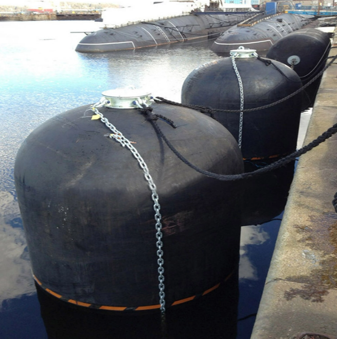
Pneumatic fenders require a structured maintenance schedule to prevent sudden failures. You must allocate personnel to perform these routine checks:
Check initial internal pressure using a calibrated gauge every three months.
Inspect the outer rubber for deep cuts exposing the synthetic tire cord.
Test the safety valve release pressure on fenders larger than 2.5 meters to prevent blowout during heavy impacts.
Examine the towing rings and swivels for metal fatigue or severe rust.
Verify the condition of the chain and tyre net, replacing worn aircraft tires and rusted shackles as needed.
Foam fenders present a different maintenance reality. They have no end fittings and no pressure vessels to monitor. This significantly reduces the ongoing labor required to keep them operational. Your maintenance team only needs to perform the following:
Conduct visual inspections of the polyurethane skin for gouges or tears.
Measure the depth of any surface abrasions to ensure the foam core remains protected.
Inspect the integral end fittings and shackle connection points for wear.
Clean marine growth from the surface to maintain visibility and performance.
Analyze the logistical advantages of pneumatic systems. You can deflate and roll pneumatic fenders. You can ship them in standard 40-foot shipping containers. This drastically reduces transport logistics and simplifies storage. Deflation allows for highly scalable deployment across global operations, making them ideal for rapid mobilization. Air-filled pneumatic fenders are significantly lighter. They require lower-capacity lifting equipment during deployment.
Foam fenders present specific logistical constraints. They are rigid structures. They maintain their full volume during transport. Larger diameters require flat racks or break-bulk shipping. This increases the upfront logistical planning required to get them to the deployment site. Foam fenders possess a dense, heavy solid core. You will need higher-capacity cranes to position and install them safely.
Follow these deployment steps for pneumatic fenders:
Unroll the deflated fender on a flat, clear quayside surface.
Connect the air compressor to the inflation valve.
Inflate to the manufacturer-specified initial pressure.
Install the chain and tyre net over the inflated body.
Lift the assembled unit using a mobile crane attached to the designated lifting eyes.
Secure the mooring chains to the quay bollards or vessel hard points.
Feature | Pneumatic Fenders | Foam-Filled Fenders |
|---|---|---|
Energy Medium | Pressurized Air | Closed-Cell Polyethylene Foam |
Puncture Risk | Deflation and total loss of function | Maintains function, will not sink |
Maintenance Needs | Regular valve and pressure checks | Minimal, visual skin inspections only |
Transport Logistics | Deflatable, fits standard shipping containers | Rigid volume, requires flat racks |
Handling Weight | Lighter, requires smaller capacity cranes | Heavier, requires larger capacity cranes |
Standardization guarantees performance reliability. Marine engineers rely on established testing protocols to mitigate operational risks. The landscape of compliance differs significantly between the two fender types. You must understand these differences to procure reliable equipment.
ISO 17357 stands as the definitive standard for pneumatic fenders. Compliance ensures consistent material quality. It mandates rigorous performance testing and strict safety parameters. Manufacturers must prove their fenders can withstand specific compression cycles without failure. The parallel compression test forces the fender to 60% or more of its diameter to verify energy absorption. The angular compression test simulates real-world berthing where vessels rarely approach perfectly parallel to the quay.
This standardization lowers procurement risk for port engineers and fleet managers. When you specify an ISO 17357 compliant fender, you know exactly how it will perform. You have documented assurance of its energy absorption and reaction force capabilities. This predictability is non-negotiable for high-risk maritime operations involving hazardous cargo.
Foam-filled fenders lack a dedicated, universal ISO standard. This requires a more diligent procurement approach. You must establish a framework for evaluating manufacturer trustworthiness to ensure you receive a reliable product that won't degrade prematurely.
Look for documented compression testing data from the manufacturer's facility. Demand third-party verification from reputable classification societies like ABS, DNV, or Lloyd's Register. Ensure the manufacturer adheres to US Navy or PIANC guidelines for solid fenders. Reliable manufacturers will provide extensive testing reports proving their foam density and skin thickness meet your specified operational demands.
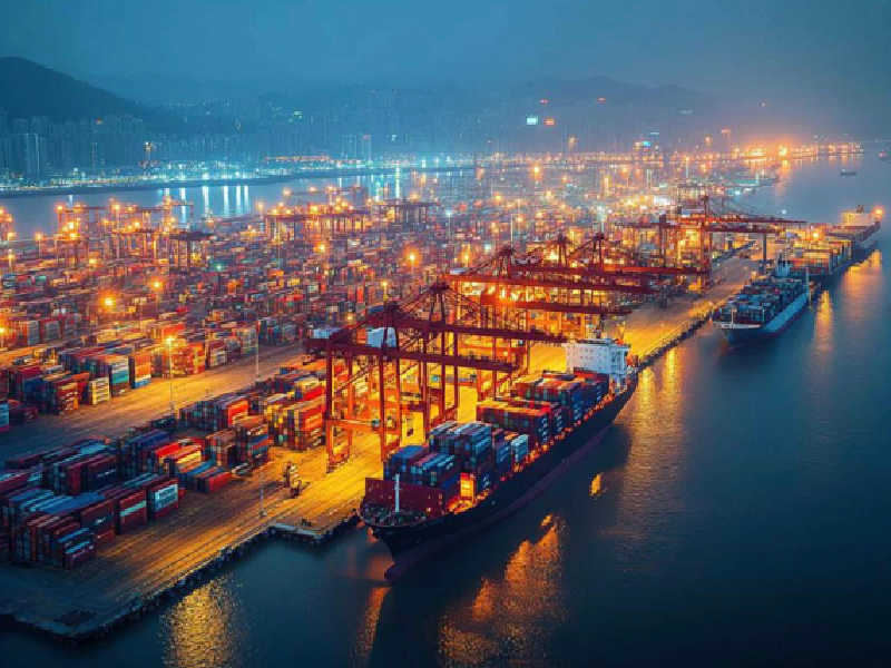
Selecting the correct fender depends entirely on the operational environment. You must analyze the specific demands of your marine application to ensure optimal protection. A fender that works perfectly in a sheltered harbor might fail catastrophically in an open-ocean transfer.
Pneumatic fenders are historically the industry standard for STS and LNG operations. Their lightweight nature allows for rapid deployment at sea. They offer high buoyancy and exceptional flexibility in dynamic wave conditions. They maintain a safe stand-off distance between vessels rolling in open water.
More importantly, they deliver predictable performance under ISO standards. LNG carriers have strict hull pressure limits due to their thin hull plates accommodating cryogenic tanks. The soft, even pressure distribution of a pneumatic fender protects these sensitive hulls during open-ocean transfers. The global standardization of Yokohama-type fenders makes them universally accepted by vessel masters worldwide.
Some environments present extreme physical hazards. Sharp protrusions, floating debris, or rough concrete structures pose constant threats. Old cargo terminals and busy river ports often have exposed rebar or jagged quay walls. In these scenarios, a pneumatic puncture would be highly probable and operationally disastrous.
Foam fenders excel in these harsh environments. The solid core eliminates the deflation risk. Even if a jagged concrete edge tears the polyurethane skin, the fender continues to absorb impact. They provide critical reliability where standard maintenance is difficult or impossible, ensuring the berth remains operational despite physical damage to the fender.
Port facilities often require unique fender dimensions to accommodate specific infrastructure. Standard cylindrical fenders might not fit narrow lock entrances or specialized dry docks. Foam fenders offer greater manufacturing flexibility for custom sizes and shapes.
Manufacturers can adjust the foam density to meet specific energy absorption requirements. They can build square, D-shaped, or custom-diameter units without the need for standardized pressure vessel molds. This makes foam technology highly adaptable for bespoke marine engineering projects and specialized docking facilities where off-the-shelf solutions fail.
Both fenders handle tidal variations well, but their specific applications diverge in sub-surface environments. Ports with extreme tidal shifts often utilize floating fenders to maintain constant protection regardless of water level changes. The fender simply rides the tide up and down the quay wall.
Submarine berthing requires specialized sub-surface protection because the hull contact point sits below the waterline. Hydro-pneumatic fenders are specifically designed for this. They utilize a water and air mixture to sit lower in the water column, providing a vertical contact face. Specially weighted foam fenders can also achieve this sub-surface positioning. You must evaluate the adaptability of both core technologies based on the exact draft and freeboard of the vessels.
Deploying a fender system involves long-term operational commitments. You must balance initial logistical efforts against ongoing maintenance labor requirements. Understanding these trade-offs prevents unexpected operational bottlenecks.
Compare the initial logistical effort against long-term operational labor. Pneumatic fenders require less initial transport effort. You can ship them deflated across the globe efficiently. However, they demand consistent maintenance labor over their lifespan. You must allocate personnel to monitor pressures and service valves regularly to prevent failures.
Foam fenders demand significant upfront transport logistics. Moving massive, rigid structures requires specialized shipping and heavy lifting coordination. However, they require near-zero maintenance labor once installed. You save significant man-hours over the operational life of the terminal by eliminating routine pressure checks and valve replacements.
Every technology carries inherent implementation risks. You must deploy specific mitigation strategies to ensure longevity and safety on the quayside.
Risk: Premature failure of pneumatic fenders due to over-pressurization. Extreme temperature fluctuations can cause internal pressure to spike, risking a blowout upon heavy impact.
Mitigation: Implement strict adherence to pressure monitoring protocols. You must utilize and regularly test safety valves for all pneumatic fenders over 2.5 meters in diameter.
Risk: Degradation of foam fender skin leading to core waterlogging over decades. Continuous abrasion against rough quay walls can eventually wear through the elastomer skin.
Mitigation: Specify high-thickness polyurethane skins during procurement. Implement routine visual abrasion checks. Utilize Chain and Tyre Nets to absorb the primary abrasive forces and protect the fender body.
Neither fender is universally superior. The choice is strictly dictated by the operational environment, logistical constraints, hull pressure limits, and your risk tolerance for maintenance versus puncture. Understanding the mechanics of these systems ensures you protect your vessels and infrastructure effectively.
Specify Pneumatic Fenders if transport logistics are complex, the application is STS/LNG, ISO-certified predictability is mandated, crane capacity is limited, and regular maintenance is feasible.
Specify Foam Fenders if the berthing environment poses a high puncture risk, maintenance resources are scarce, custom sizing is required, and continuous operation post-damage is a critical safety requirement.
For marine operators seeking dependable fender solutions for demanding berthing environments, Hongruntong Marine provides marine fender products and solutions designed to support vessel protection and safe berthing operations. With a focus on marine applications and practical operational requirements, the company serves customers looking for reliable fender solutions for ports, terminals, vessels, and other marine projects.
Take the following steps to finalize your procurement strategy:
Calculate the maximum berthing energy for your specific terminal using the displacement tonnage and approach velocity of your largest expected vessel.
Verify the allowable hull pressure limits for the ships frequenting your berths to determine the maximum acceptable reaction force.
Assess your quayside infrastructure for puncture hazards, including exposed rebar, sharp concrete edges, or heavy debris flow.
Inventory your available lifting equipment to ensure you have the crane capacity required for deployment and retrieval.
A: Pneumatic fenders use pressurized air to absorb impact, offering high flexibility but carrying a risk of deflation if punctured. Foam fenders use a closed-cell solid foam core that compresses to absorb energy. They cannot deflate and will maintain functionality even if the outer skin is breached.
A: Pneumatic fenders are significantly lighter because their core is filled with air. This makes them easier to handle and requires lower-capacity cranes for deployment. Foam fenders have a dense, solid core, making them much heavier and requiring robust lifting equipment.
A: Pneumatic fenders can be deflated, rolled, and shipped in standard containers, making transport highly efficient. Foam fenders are rigid and maintain their full volume. Large foam fenders require specialized flat racks or break-bulk shipping, which requires more complex logistical planning.
A: Pneumatic fenders are the industry standard for STS transfers. Their lightweight nature, high buoyancy, and ability to conform to hull shapes make them ideal. Furthermore, compliance with ISO 17357 ensures predictable, safe performance during dynamic open-ocean operations.
A: Yes. Foam fenders offer excellent manufacturing flexibility. Because they do not rely on standardized pressure vessel molds, manufacturers can easily customize their size, shape, and foam density to meet specific energy absorption and spatial requirements.
A: Foam fenders require minimal maintenance compared to pneumatic systems. Because they lack internal air pressure, safety valves, and ball valves, they do not require pressure checks. Maintenance is generally limited to routine visual inspections for skin abrasions or tears.


