

Views: 0 Author: Site Editor Publish Time: 2026-08-21 Origin: Site


Inadequate marine fendering directly correlates to accelerated infrastructure degradation, vessel hull damage, and costly terminal downtime. Port engineers and terminal operators must balance the need for high energy absorption and low reaction force with strict constraints on long-term operational expenditure, initial capital expenditure, and existing marine construction limitations. Upgrading dock framing to support heavier systems is rarely feasible without massive operational disruptions.
We present a technical, evidence-based comparison between closed-cell foam fenders and traditional rubber fenders, evaluating both solid and pneumatic variants. You will learn how to determine the optimal fendering system based on specific terminal requirements, vessel traffic, and environmental conditions. This guide provides actionable engineering insights to protect your marine infrastructure reliably.
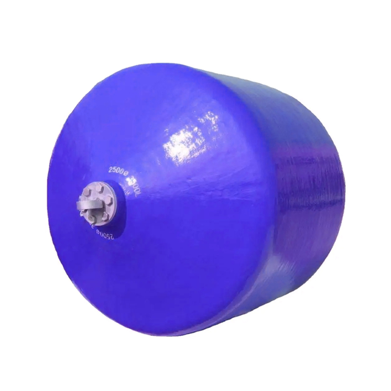
Puncture Resilience & Toughness: A foam fender utilizes a closed-cell core that prevents sinking and maintains energy absorption even if the tough outer polyurethane skin is breached or cut, unlike pneumatic rubber alternatives.
Infrastructure Load & Buoyancy: The lightweight, highly buoyant nature of foam fenders significantly reduces deadweight stress on existing dock framing and quay walls, often eliminating the need for costly marine construction upgrades.
Performance Stability: Foam fenders deliver consistent, predictable performance across varying compression levels, whereas pneumatic systems require continuous pressure monitoring to maintain optimal reaction forces.
Application Specificity: The selection between foam and rubber systems hinges on site-specific variables, including port typology, tidal ranges, stand-off distance requirements, and the hull pressure tolerances of the berthing vessels.
Table of Contents
You cannot select a fender without first calculating the kinetic energy of approaching vessels. Engineers determine this baseline using the vessel's displacement tonnage, approach velocity, and approach angle. Large vessels carry massive momentum even at fractional speeds. When a ship strikes the berth, the fendering system must absorb the combined energy of the vessel and the entrained water moving alongside it.
To accurately model this kinetic energy, marine structural engineers evaluate several distinct variables:
Displacement Tonnage: The total mass of the vessel when fully loaded.
Approach Velocity: The speed at which the vessel moves toward the berth, usually measured in meters per second.
Hydrodynamic Mass Coefficient: The added mass of the water moving with the ship, which significantly increases the total kinetic energy.
Eccentricity Factor: A calculation that accounts for the vessel striking the fender at an angle rather than dead-on, which dissipates some energy through rotation.
Berth Configuration Factor: The cushioning effect provided by the water trapped between the hull and the quay wall just before impact.
Failure to accurately model these variables leads to undersized fenders. Undersized systems bottom out during impact. This transfers destructive force directly into the concrete quay wall, causing immediate spalling or structural failure.
The core metric of any marine fender is its energy absorption to reaction force ratio. You want to maximize kinetic energy dissipation while minimizing the force pushed back against the quay wall and the vessel hull. High reaction forces crack concrete structures. They buckle steel pilings. They dent ship hulls.
A highly efficient fender absorbs massive energy through controlled deformation but keeps the peak reaction force low. You must map the performance curve of the fender. Look for a linear and predictable energy absorption curve. Sudden spikes in reaction force at high compression levels indicate an inefficient system. When evaluating technical data sheets, always compare the reaction force at 60% and 70% compression. This reveals how the material behaves under severe, unexpected loads.
The specific type of port dictates your fender selection. Different operations impose entirely different stress profiles on marine infrastructure.
RoRo Terminals: Roll-on/Roll-off operations require continuous fendering along the berth to accommodate varying ramp positions and constant vessel movement.
Container Terminals: These facilities handle massive vessels that demand high energy absorption at distinct hard points along the quay.
Bulk Terminals: Facilities handling coal, grain, or ore deal with abrasive cargoes and heavy dust. They require durable exterior skins that resist severe abrasion.
Naval Bases: Military facilities host vessels with sensitive, thin hulls that cannot tolerate high localized pressure. They require extremely soft initial contact.
You must also evaluate the structural integrity of your existing dock framing. Aging timber or degraded concrete cannot support the heavy deadweight of massive solid rubber systems. You need lightweight alternatives to prevent pulling the anchors out of the wall under heavy shear loads.
Different vessels tolerate different levels of contact pressure. Cruise ships, naval destroyers, and LNG carriers feature relatively thin hull plating. If a fender exerts too much pressure over a small area, it will permanently deform the hull. Oil tankers and bulk carriers possess thicker, stronger hulls capable of withstanding higher localized forces.
You must evaluate the allowable contact pressure for your target vessel classes. Fender footprint directly impacts load distribution. A larger contact area spreads the reaction force safely across multiple hull frames. You must match the fender's stiffness and surface area to the structural limits of the ships visiting your terminal. Using a rigid, small-footprint fender on a thin-hulled vessel guarantees expensive damage claims.
Marine environments destroy inferior materials. Fenders face continuous saltwater exposure. They endure intense ultraviolet radiation from the sun. They suffer impacts from floating debris and ice. You must assess how extreme tidal fluctuations affect fender positioning.
Fixed solid rubber fenders might become submerged during high tide. They might hang uselessly above the waterline during low tide. Floating systems adjust naturally to water levels. You must ensure the materials resist marine growth and do not degrade when covered in oil or chemical spills. Material integrity dictates long-term reliability. A fender that degrades in sunlight or hardens in freezing temperatures will fail when you need it most.
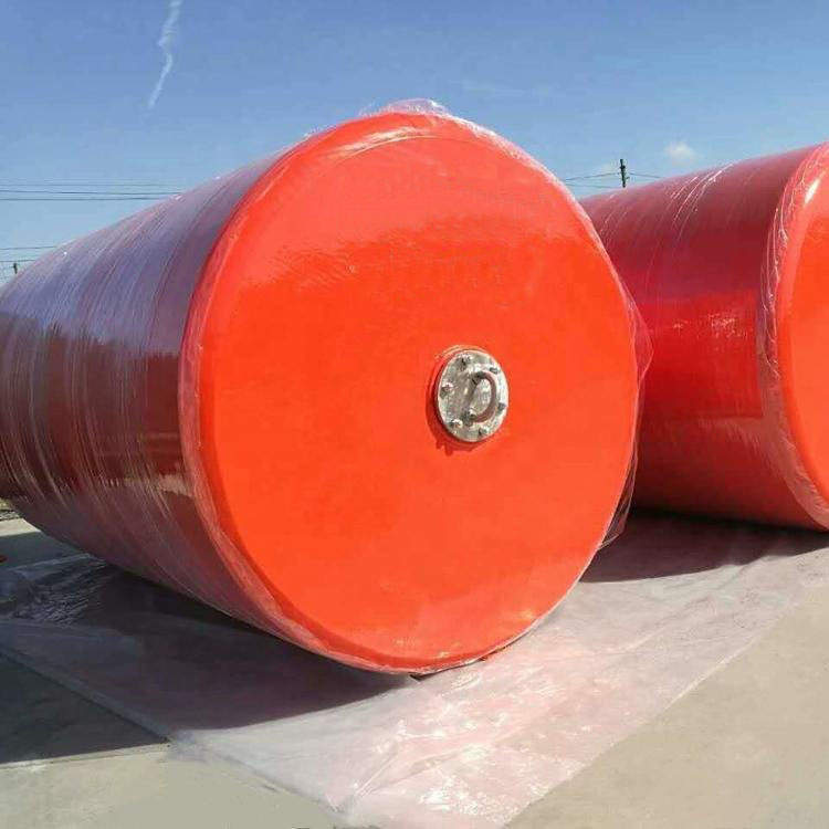
A Foam Fender operates on the principle of physical compression. The anatomy consists of three main components engineered to work together under extreme stress.
First, the core utilizes closed-cell polyethylene foam. This matrix contains thousands of individual, sealed air pockets. Second, a tough, abrasion-resistant reinforced polyurethane elastomer skin encapsulates the core. Manufacturers often reinforce this skin with continuous nylon filaments for extreme tear resistance. Third, internal steel or nylon structural components distribute the load to the mounting hardware.
When a vessel strikes, the foam matrix compresses. It absorbs heavy impacts smoothly. The closed-cell nature ensures high buoyancy and structural memory. The fender returns to its original shape after impact. It maintains consistent performance even if the exterior sustains deep cuts. Water cannot flood the internal structure because the individual cells do not share air or moisture.
Rubber fenders rely on entirely different mechanical principles. Solid molded rubber fenders include cone, cell, and arch profiles. These systems rely on the geometric buckling of vulcanized rubber. As the ship pushes against the fender, the rubber shape resists until it reaches a critical point. It then buckles and folds to absorb the energy. This requires precise alignment during impact.
Pneumatic rubber fenders operate differently. They consist of a reinforced rubber envelope filled with pressurized air. They rely on the compression of this internal air volume. As the fender compresses, the internal air pressure rises. This provides a soft initial contact. However, the reaction force spikes rapidly as the internal pressure increases near maximum compression. The entire system depends on the integrity of the outer envelope and the air valves.
You must evaluate how these systems behave under maximum load. A Foam Fender delivers a linear and predictable energy absorption curve. As compression increases, the resistance builds smoothly. It does not suffer from sudden performance drops if over-compressed. This makes it highly reliable for large vessels approaching at awkward angles.
Solid rubber fenders require specific geometric deformation. If a vessel strikes a cone fender at a severe angle, the rubber may not buckle correctly. This reduces energy absorption and increases shear stress on the mounting bolts. Pneumatic rubber provides very soft initial contact. This is excellent for ship-to-ship transfers. However, the reaction force curve is non-linear. It ramps up aggressively as the air volume decreases, which can push back violently against the vessel hull if compressed too far.
Marine operations are brutal. Fenders scrape against rusty hulls, sharp protrusions, and broken pilings. Foam fenders feature an unsinkable design. The tough outer polyurethane skin resists severe abrasion far better than standard rubber. If a sharp hull protrusion lacerates the skin, the closed-cell structure prevents water ingress. The fender continues to float and absorb energy.
Pneumatic systems are highly vulnerable to deflation. A single puncture from a sharp object releases the air pressure. The fender instantly loses all energy absorption capability. It becomes a flat piece of rubber trapped between a massive ship and a concrete wall. Solid rubber resists punctures but suffers from abrasive wear. Over time, UV exposure and ozone cause the surface rubber to crack and degrade, leading to structural fatigue.
Maintenance drains operational resources. Foam fenders offer a near-zero maintenance profile. You only need to perform periodic visual inspections of the outer skin and the mounting hardware. They do not require inflation checks or safety valve testing.
Pneumatic systems demand strict routine maintenance. Crews must regularly check air pressure. They must test pressure relief valves to prevent explosive ruptures during heavy impacts. They must inspect the protective chain-and-tire nets for broken links and worn tires. Solid rubber requires monitoring for structural fatigue. You must inspect the anchor bolts for corrosion. If a solid rubber fender sustains heavy shear damage, you must replace the entire unit.
Performance Metric |
Closed-Cell Foam Fender |
Solid Rubber Fender |
Pneumatic Rubber Fender |
|---|---|---|---|
Puncture Resilience |
Excellent (Unsinkable, maintains function) |
High (Solid mass, no air to lose) |
Low (Deflates entirely upon puncture) |
Maintenance Burden |
Very Low (Visual inspections only) |
Low to Medium (Bolt checks, shear monitoring) |
High (Pressure checks, valve tests, net repairs) |
Reaction Force Curve |
Linear and smooth |
Buckling point dependent |
Non-linear (spikes at high compression) |
Hull Pressure |
Very Low (Gentle on thin hulls) |
Medium to High (Depends on frontal panel) |
Low (Soft initial contact) |
Buoyancy & Tidal Adaptation |
High (Floats naturally with tide) |
None (Fixed to quay wall) |
High (Floats naturally with tide) |
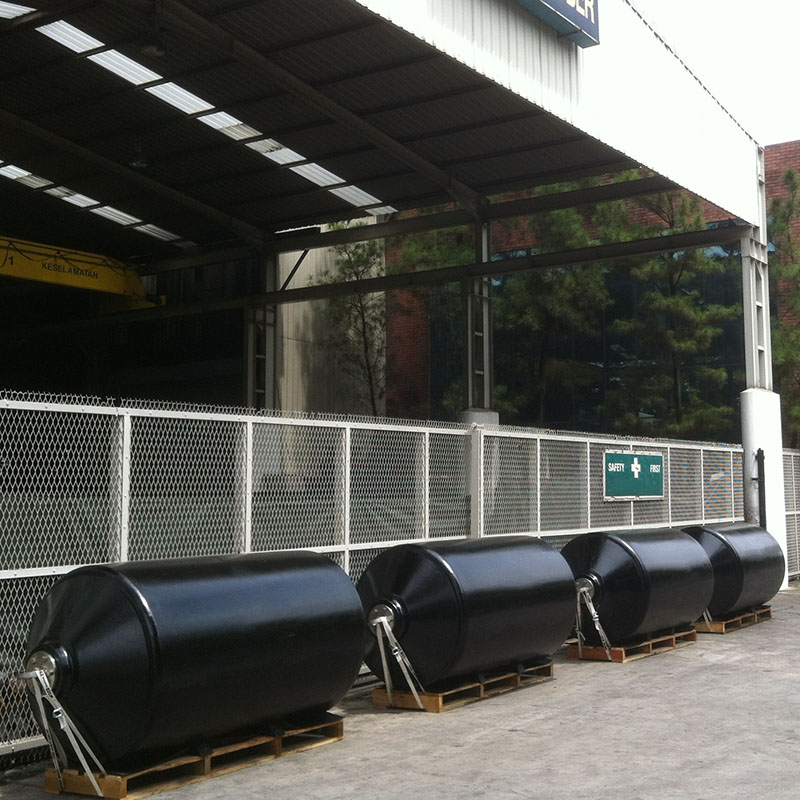
Procurement decisions often start with upfront costs. Solid rubber units are mass-produced and generally offer the lowest initial purchase price. However, this price rarely includes the heavy steel frontal panels and complex anchoring systems required for installation. Custom-manufactured foam fenders carry a higher initial procurement cost due to the specialized polyurethane elastomers and closed-cell foam cores. Pneumatic fenders sit in the middle, but require expensive chain-and-tire nets to protect the rubber envelope from immediate destruction.
You must account for the hidden labor required to keep fendering systems operational over a long lifespan. Pneumatic systems consume significant maintenance hours. Your crews must deploy specialized equipment to test valves and reinflate bladders. They must replace worn tires and rusted chains on the protective nets. This diverts labor from other terminal operations.
Foam systems eliminate these ongoing labor requirements. Once installed, they function passively. You allocate your maintenance teams to more pressing infrastructure needs. The reduction in continuous labor directly improves terminal efficiency and lowers long-term operational expenses.
Heavy fendering systems impose massive deadweight loads on existing structures. Solid rubber cell and cone fenders require extensive steel frontal panels to distribute hull pressure. This entire assembly hangs off the quay wall. If you operate an aging terminal, the concrete may not support this weight. You face the prospect of drilling new anchor points, pouring reinforced concrete, or driving new steel pilings.
A highly buoyant foam fender floats on the water. It transfers virtually zero deadweight to the dock framing. You secure it with simple mooring chains or guide poles. This lightweight profile allows you to upgrade your energy absorption capacity without rebuilding your quay wall, saving millions in marine construction costs.
Fender failure shuts down berths. You must quantify the operational risk of a catastrophic blowout. If a pneumatic fender punctures during a berthing maneuver, the vessel strikes the concrete. You face immediate structural repairs to the terminal. You face claims for vessel hull damage. You lose revenue for every day that berth remains unusable.
Emergency replacement logistics compound the problem. Sourcing and shipping a replacement pneumatic or solid rubber unit takes weeks. Foam fenders mitigate this risk. Even if severely damaged, they continue to function as a physical barrier. They prevent metal-to-concrete contact. You keep the berth open while planning a scheduled replacement.
Retrofitting heavy fenders onto aging quay walls compromises structural integrity. The primary risk involves anchor bolt pull-out under heavy shear loads. When a vessel slides along a solid rubber fender, it generates massive friction. This friction pulls laterally on the mounting hardware.
To mitigate this, you must conduct comprehensive structural load assessments before installation. Utilize the lightweight nature of a foam fender to reduce deadweight stress. Apply expert best practices for dock framing integration. Use low-friction UHMW-PE pads on frontal panels if using solid rubber. For floating foam systems, ensure the mooring chains have sufficient slack to accommodate tidal movement without binding.
Ports with large tidal ranges face unique challenges. Fixed solid rubber fenders risk becoming submerged during high tide. Vessels might strike the unprotected wall above the fender. During low tide, the fenders might hang suspended above the waterline. Smaller vessels can slip underneath them, crushing their superstructures as the tide rises.
To mitigate this risk, implement highly buoyant floating foam fender systems. Mount them on vertical guide poles or use chain-and-tire nets secured to the quay. These systems naturally and reliably adjust to water levels. The fender always remains exactly at the waterline, providing continuous protection regardless of the tidal state.
A mismatch between fender stiffness and vessel hull strength causes severe damage. If you install rigid solid rubber fenders at a terminal serving thin-hulled naval ships or passenger ferries, the high reaction force will dent the hull plating. You must match the fender to the traffic.
To mitigate compatibility risks, specify low-density foam cores for sensitive vessels. A lower density core compresses more easily, guaranteeing low reaction forces at maximum compression. For terminals handling massive crude carriers, specify high-density foam cores or large pneumatic systems to absorb the immense kinetic energy without bottoming out.
Selecting the correct marine fendering system dictates the long-term structural health of your terminal. There is no universal solution. However, the foam fender stands as objectively superior for terminals prioritizing low maintenance, puncture resilience, high buoyancy, and consistent performance under harsh conditions. Solid rubber remains viable for standard-duty applications with fixed water levels. Pneumatic systems excel in temporary ship-to-ship operations where soft initial contact is required.
For projects requiring dependable marine protection solutions, Hongruntong Marine provides marine fender solutions designed to support a wide range of port, terminal, dock, and vessel applications. With a focus on practical marine protection requirements, the company helps customers identify suitable fender solutions based on operational conditions and project-specific needs.
Take the following next steps to secure your marine infrastructure:
Conduct a site-specific berthing energy analysis using the maximum displacement and approach velocity of your largest expected vessels.
Consult with a marine structural engineer to evaluate the deadweight and pull-out load capacity of your existing quay walls.
Request technical data sheets from manufacturers to compare the energy absorption and reaction force curves of specific foam fender densities.
Audit your current maintenance capabilities to determine if your team can support the continuous inspection requirements of pneumatic systems.
A: A high-quality foam fender typically lasts 15 to 20 years with minimal maintenance. The tough polyurethane skin resists UV and ozone degradation. Solid rubber fenders last similarly but suffer from ozone cracking and abrasive wear over time. Pneumatic fenders require tire net replacements every few years and are highly susceptible to premature failure from punctures.
A: No. The core consists of closed-cell polyethylene foam. Each microscopic air pocket is completely sealed. Even if the outer skin sustains deep lacerations from a sharp hull protrusion, water cannot penetrate the foam matrix. The fender remains highly buoyant and continues to absorb impact energy safely.
A: Foam fenders excel in naval bases, cruise terminals, and ports with extreme tides due to their low hull pressure and floating design. Solid rubber fenders are standard for container and bulk terminals with robust concrete quay walls. Pneumatic fenders are the industry standard for temporary ship-to-ship transfer operations.
A: It drastically reduces deadweight loads on the dock framing. Aging timber or degraded concrete walls often cannot support the heavy steel panels and solid mass of traditional rubber systems. Floating foam systems transfer almost zero vertical weight to the structure, eliminating the need for expensive structural reinforcements.
A: High-quality closed-cell foam and polyurethane elastomers maintain stable performance across a wide temperature range, typically from -40°C to +60°C. Solid rubber can become significantly stiffer in freezing temperatures, which increases the reaction force transferred to the vessel hull. Pneumatic fenders require pressure adjustments based on ambient temperature changes.
A: Yes. While pneumatic fenders are traditionally used for ship-to-ship operations, lightweight foam fenders are increasingly deployed. They offer the distinct advantage of being unsinkable during high-risk open-ocean transfers. They provide excellent energy absorption and will not deflate if pinched between two rolling vessel hulls.
A: Engineers calculate the kinetic energy of the berthing vessel using its mass, approach velocity, and hydrodynamic mass coefficient. They then select a fender size and foam density that provides an energy absorption rating greater than the calculated kinetic energy, while ensuring the resulting reaction force remains below the hull pressure limits.


