

Views: 0 Author: Site Editor Publish Time: 2026-08-21 Origin: Site


The physics of berthing massive commercial vessels leaves zero margin for error; a miscalculation in energy absorption can result in millions of dollars in hull damage or port infrastructure failure. Selecting the correct size for Pneumatic Fenders is not a simple chart-lookup exercise. Undersized fenders risk catastrophic failure under dynamic loads, while oversized fenders create unnecessary standoff distances, complicate loading operations, and inflate capital expenditure.
To protect maritime assets and ensure operational continuity, procurement and marine engineering teams must evaluate fender sizing through a strict framework of vessel displacement, approach velocity, environmental conditions, port infrastructure, and certified performance metrics. We rely on hard data and site-specific dynamic mooring analyses to keep ship-to-shore and ship-to-ship transfers safe. You must approach this selection process as a strict engineering calculation to guarantee reliable performance across all maritime environments.

Fender sizing is dictated primarily by the vessel's kinetic energy during berthing, which determines the required Guaranteed Energy Absorption (GEA).
Standard dimensions (Diameter × Length) must be paired with the correct initial internal pressure (typically 50 kPa or 80 kPa) to meet specific Hull Pressure limits.
Vessel type and Deadweight Tonnage (DWT) dictate not only the size but the spacing arrangement—ranging from 5–10% of ship length for smaller vessels to 25–50% for larger ships.
Procurement decisions must mandate strict adherence to ISO 17357-1:2014 standards to mitigate the severe operational risks associated with substandard or counterfeit manufacturing.
Table of Contents
Marine engineers determine fender size by first calculating the vessel's kinetic energy during berthing. You must use the standard mathematical formula: E = 0.5 × M × V⊃2; × C. In this equation, 'M' represents the vessel's mass or displacement tonnage. 'V' stands for the approach velocity at the moment of impact. 'C' is a combined coefficient that accounts for multiple dynamic variables during the berthing process.
To get an accurate 'C' value, you must multiply four distinct factors. The eccentricity factor (Ce) accounts for the vessel's rotational movement when the bow or stern strikes the fender first. The virtual mass factor (Cm) accounts for the mass of the water moving alongside the ship. The softness factor (Cs) represents the energy absorbed by the deformation of the ship's hull. Finally, the berth configuration factor (Cc) accounts for the water cushion effect between the ship and a solid quay wall.
Vessel mass and approach speed form the baseline for selecting Pneumatic Fenders. A fully loaded Very Large Crude Carrier (VLCC) moving at just 0.15 meters per second generates massive kinetic energy. You must accurately calculate these variables to establish the minimum energy absorption requirements for your docking system. Guesswork here leads directly to structural failure.
The ultimate success metric for any fender system lies in balancing energy absorption with reaction force. Guaranteed Energy Absorption (GEA) measures the fender's ability to dissipate the kinetic energy of the incoming vessel. Reaction Force (RF) measures the pushback exerted against the ship's hull and the port structure during compression.
You must maximize energy absorption while keeping the reaction force strictly below the vessel's allowable hull pressure. Different vessels have different tolerances. A rugged bulk carrier might withstand 200 kN/m², while a specialized LNG carrier with a membrane containment system might only tolerate 150 kN/m². Exceeding hull pressure limits causes permanent structural deformation. Engineers must select a fender size that compresses sufficiently to absorb the impact without transferring destructive force back into the ship's framing.
Standard berthing calculations assume ideal conditions. Real-world maritime operations require a substantial safety margin for abnormal impacts. You must factor in accidental high-speed approaches, heavy windage pushing the vessel, and severe weather berthing scenarios. A sudden squall can easily double the approach velocity of a vessel in the final seconds of mooring.
Industry standards recommend applying a safety factor of 1.25 to 2.0 to your baseline kinetic energy calculations. This abnormal impact allowance ensures the fender will not burst or bottom out during a storm surge or mechanical failure. Sizing up provides critical insurance against unpredictable dynamic loads. When you stand on a quay during a heavy swell, you quickly realize why these safety margins exist.
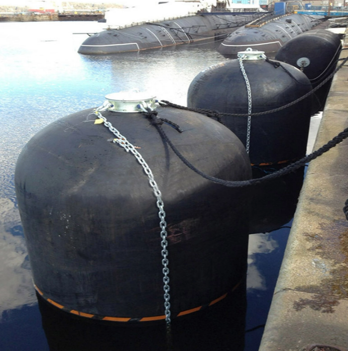
Manufacturers express standard sizing nomenclature as Diameter × Length (D × L). You will typically see dimensions listed in meters, such as 2.5 × 5.5 m, or in millimeters, such as 3300 × 6500 mm. The diameter dictates the standoff distance between the vessel and the quay or between two vessels during ship-to-ship transfers. You need enough standoff to keep overhanging ship structures, like bridge wings or loading manifolds, from striking shore cranes.
The length determines the load distribution along the hull. A longer fender spreads the reaction force over a larger surface area, reducing localized hull pressure. You must match the D × L specifications to the specific architectural constraints of your terminal and the hull curvature of your fleet. A short, fat fender might provide the right standoff but concentrate too much force on a single hull frame.
Reading standard performance tables requires cross-referencing physical dimensions against performance metrics. You must align the D × L measurements with the Guaranteed Energy Absorption (GEA) and Reaction Force (RF) columns. This verification ensures the physical footprint matches the operational energy requirements. Below is a reference table demonstrating how performance scales with size and internal pressure.
Size (Diameter × Length) | Initial Pressure | Guaranteed Energy Absorption (kN·m) | Reaction Force (kN) |
|---|---|---|---|
1.0 × 2.0 m | 50 kPa | 37 | 224 |
1.0 × 2.0 m | 80 kPa | 48 | 302 |
2.0 × 3.5 m | 50 kPa | 263 | 844 |
2.0 × 3.5 m | 80 kPa | 345 | 1140 |
3.3 × 6.5 m | 50 kPa | 1330 | 2590 |
3.3 × 6.5 m | 80 kPa | 1740 | 3490 |
4.5 × 9.0 m | 50 kPa | 3480 | 4960 |
4.5 × 9.0 m | 80 kPa | 4550 | 6690 |
Standard pneumatic fenders come in two primary initial internal pressure configurations: 50 kPa (P50) and 80 kPa (P80). The initial pressure dictates the stiffness and energy capacity of the fender before any external load is applied. P50 fenders offer a softer initial contact, making them suitable for vessels with lower allowable hull pressures. They compress more easily during the initial stages of berthing.
Higher initial pressure (P80) increases the energy absorption capacity within the exact same physical footprint. You should specify P80 configurations when terminal space limits the maximum allowable fender diameter, but the berthing energy demands remain high. The P80 rating allows you to handle heavier vessels without increasing the standoff distance. However, you must verify that the vessel's hull can withstand the correspondingly higher reaction force.
You must choose between Chain and Tyre Net (CTN) fenders and Sling Type fenders based on operational environments. CTN fenders feature a protective lattice of chains and heavy-duty rubber tires. This configuration provides superior protection against abrasion, cuts, and harsh weather, making it mandatory for heavy-duty protection and offshore ship-to-ship transfers.
When inspecting or specifying a CTN configuration, you must verify several components:
The longitudinal chains must be high-tensile galvanized steel to resist saltwater corrosion.
The rubber sleeves over the chains must be intact to prevent the steel from gouging the fender body.
The aircraft or truck tires used in the net must be uniform in size to ensure even load distribution.
The towing rings at both ends must be rated for the maximum anticipated pull load during deployment.
Sling Type fenders lack the external net. They feature attachment eyes directly integrated into the outer rubber layers. This lightweight design is ideal for vessels sensitive to scratching, such as luxury yachts or naval ships. Sling types are easier to handle and deploy but require more careful monitoring for external jacket wear.
Barges, tugs, and coastal freighters require specific sizing parameters. These vessels typically operate under 20,000 Deadweight Tonnage (DWT) and engage in high-frequency berthing. You must prioritize rapid deployment and tighter spacing requirements. These ships often have lower freeboards, meaning a massive fender would sit too high in the water and potentially roll onto the deck.
For these applications, standard sizes ranging from 1.0 × 2.0 m to 2.0 × 3.5 m are highly effective. The smaller diameter ensures the fenders do not interfere with low freeboards. You must arrange them closely together to accommodate the shorter parallel body length of these vessels. Frequent berthing also means these fenders endure high cycle fatigue, so specifying a high-quality outer rubber compound is non-negotiable.
Massive displacement vessels demand the largest available fender sizes. Very Large Crude Carriers (VLCCs) and heavy bulk carriers generate immense kinetic energy even at minimal approach speeds. You must deploy large-diameter fenders, typically 3.3 × 6.5 m or 4.5 × 9.0 m. Anything smaller will bottom out instantly under the weight of a fully loaded tanker.
These massive units safely dissipate extreme kinetic energy. They also provide the necessary standoff distance to prevent the ship's flared bow or overhanging structures from striking the gantry cranes. Large diameters ensure stable docking operations under heavy wind loads that push the massive hull against the berth. When a 300,000 DWT vessel leans on the quay, the fender must maintain its structural integrity at 60% compression.
Roll-on/Roll-off (Ro-Ro) vessels and passenger ferries present unique berthing challenges. They feature large windage areas that make them susceptible to sudden gusts during approach. Furthermore, they require precise ramp-alignment with the shore infrastructure. If the fender allows too much movement, the loading ramp can slip off the quay, causing a catastrophic accident.
You must select fenders that dictate precise standoff distances to allow loading ramps to lower safely onto the quay. Lower reaction forces are critical here, as ferry hulls are often thinner than those of crude carriers. Medium-sized P50 fenders generally provide the necessary balance of soft contact and strict alignment control. You will often see these installed in combination with fixed rubber panels to lock the vessel in place.
Naval vessels, submarines, and stealth frigates require specialized sizing considerations. These ships often feature sensitive hull coatings, acoustic tiles, or radar-absorbent materials. Standard black rubber fenders can leave permanent marks or damage these specialized surfaces. A single scratch on an acoustic tile can compromise a submarine's stealth capabilities.
You must specify grey, non-marking Pneumatic Fenders for these fleets. Submarines require deep-draft or hydro-pneumatic fenders installed vertically to protect their underwater hulls. Low-pressure configurations are strictly enforced to prevent localized crushing of sensitive sonar domes and external arrays. The sizing must account for the unique teardrop hull shape of modern submarines, which requires a much deeper contact point than surface vessels.
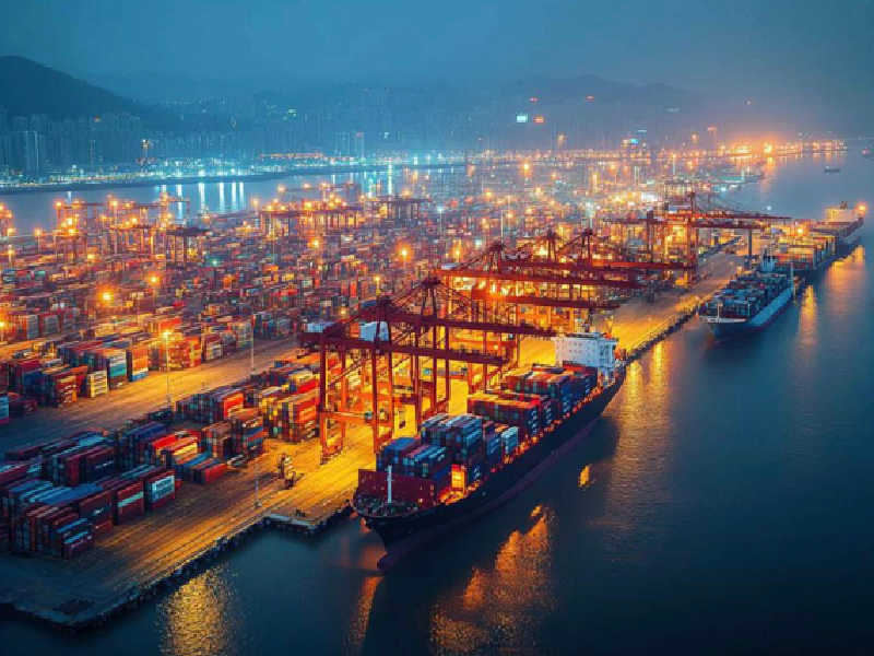
A vessel rarely approaches a berth perfectly parallel. A steep berthing angle, typically greater than 15 degrees, dramatically alters the compression dynamics. The primary point-of-contact fender absorbs a disproportionate amount of the total kinetic energy. Instead of the load spreading across three or four fenders, a single unit takes the entire initial impact.
Angular impacts reduce the effective energy absorption capacity of the fender. You must upsize the specifications to account for this angular compression. If your terminal frequently experiences steep approach angles due to narrow turning basins, select a fender with a GEA rating at least 20% higher than the baseline parallel calculation. Failing to account for angular impact is a leading cause of premature fender blowouts.
Extreme tidal ranges and heavy swells dictate strict diameter requirements. As the tide drops, a vessel moves vertically against the quay. If the fender diameter is too small, the vessel's hull curvature might slip under or over the fender. This results in the ship grinding directly against the concrete dock.
You must select larger diameter fenders to maintain continuous contact during extreme tidal shifts. In heavy sea states, the vessel will roll and pitch while moored. A larger D × L footprint prevents the fender from being squeezed out of position during loading and unloading operations. For locations with massive tidal shifts, engineers often specify floating pneumatic fenders because they rise and fall naturally with the water level, eliminating the need for complex sliding tracks.
The architectural design of the terminal directly influences fender selection. Solid quay walls provide a continuous backing surface, allowing for standard cylindrical compression. Open pile jetties and monopile dolphins present isolated contact points. You cannot install a small fender on a widely spaced monopile structure, or it will simply push through the gap.
When installing on monopiles, you must ensure the fender length bridges the structural gaps adequately. You must also calculate the maximum compression allowance. The fender diameter must remain large enough at 60% compression to prevent the ship's hull from making physical contact with the concrete or steel infrastructure. Always measure the distance from the face of the pile to the edge of the deck overhang.
Ship-to-Ship (STS) transfers involve dynamic, dual-moving-body physics. Both vessels roll, heave, and sway independently in open water. This requires highly resilient, standardized offshore sizes, almost exclusively utilizing heavy-duty CTN configurations to withstand constant friction. The fenders must absorb the relative kinetic energy of both moving masses.
Ship-to-Shore (STQ) docking involves a static barrier. The quay does not move, meaning the fender absorbs the entirety of the vessel's kinetic energy against a rigid backing. STQ operations often utilize a mix of sling-type and CTN fenders, depending on the specific berth design and historical weather patterns at the port. The rigid backing of a STQ operation means the fender will reach its maximum reaction force much faster than in an STS scenario.
Determining the correct quantity of fenders requires strict adherence to engineering rules of thumb based on ship length. You must ensure the vessel's parallel body length is adequately supported to prevent rotational pivoting during mooring. A ship pivoting on a single fender acts like a massive lever, tearing mooring lines and damaging deck hardware.
For vessels under 20,000 tons, space the fenders at intervals equal to 5–10% of the ship's total length. For larger vessels exceeding 20,000 tons, increase the spacing to 25–50% of the ship's length. This spacing guarantees that at least two fenders bear the load simultaneously regardless of the impact angle. Always verify the parallel mid-body length of the specific vessels calling at your terminal, as hull shapes vary wildly between bulkers and container ships.
Improper spacing leads to isolated point-loading. If fenders are placed too far apart, the hull may bridge between them, concentrating massive force on a single frame. This isolated pressure causes hull buckling and internal structural failure. You will see the ship's steel plating permanently dented between the internal ribs.
You must arrange fenders to ensure continuous hull support during tidal shifts and cargo weight changes. As a ship loads cargo, its draft increases, altering the contact point on the fender. The arrangement must maintain a distributed load across multiple bulkheads throughout the entire turnaround cycle. Proper load distribution extends the lifespan of both the fender and the vessel.
Primary fenders handle the broadside impact, but secondary fenders protect the extremities. You should strategically place smaller "baby" pneumatic fenders at the bow and stern. These secondary units protect against rotational impacts during final mooring adjustments. They keep the flared bow from striking the dock as the stern is pulled in by the tugs.
Standby fenders are also critical for operational readiness. Terminals should maintain a reserve of fully inflated, certified fenders. If a primary fender sustains damage from a severe storm or an accidental sharp-object puncture, immediate replacement prevents costly port downtime. Waiting weeks for a replacement fender to ship means turning away lucrative vessel traffic.
Selecting the right fender is only half the equation. The installation hardware must match the fender's maximum reaction force. A massive 4.5 × 9.0 m fender is useless if the mooring rings rip out of the concrete quay during compression. The hardware is often the weakest link in the mooring system.
You must specify appropriately rated mooring rings, chains, guy ropes, and shackles. The Safe Working Load (SWL) of all mounting hardware must exceed the maximum reaction force of the fender. Always use galvanized or marine-grade stainless steel hardware to prevent catastrophic failure due to saltwater corrosion. Inspect the U-bolts and pad eyes annually for stress fractures and rust degradation.
Fender selection directly impacts the operational reliability of the entire maritime facility. Deploying premium, correctly sized fenders protects against the catastrophic physical risks of hull breaches, cargo spills, and structural dock failure. A single failure during a crude oil transfer can result in an environmental disaster and months of port closure.
An undersized fender may burst under the pressure of a fully loaded bulk carrier. The resulting kinetic transfer will crush the quay wall and rupture the vessel's hull. Prioritizing exact engineering specifications over immediate availability ensures long-term lifecycle protection for maritime assets. You must view these fenders as critical safety equipment, not generic rubber bumpers.
Pneumatic fenders require strict, ongoing operational maintenance to retain their energy absorption capabilities. You cannot install them and ignore them. Routine inspections must verify internal pressure levels, ensuring they remain at the specified 50 kPa or 80 kPa baseline. A fender that loses 20% of its internal pressure loses a massive portion of its energy absorption capacity.
Maintenance teams must regularly service the safety valves. These valves release excess internal pressure during extreme compression to prevent the rubber body from bursting. You must also schedule periodic outer net replacements, as the chains and tires degrade rapidly from constant friction and saltwater exposure. Keep a detailed log of all pressure checks and valve inspections to satisfy maritime insurance requirements.
The maritime industry faces severe risks from non-compliant and counterfeit fenders. Substandard manufacturing leads to inconsistent rubber thickness, weak end-flanges, and premature fatigue failure. You must demand strict adherence to the ISO 17357-1:2014 standard. This standard dictates the exact manufacturing, testing, and performance criteria for high-pressure floating pneumatic rubber fenders.
Procurement teams must verify authenticity through rigorous documentation. Demand certified testing certificates for material fatigue, parallel compression, angular compression, and pressure recovery. Authentic manufacturers will readily provide third-party inspection reports proving their products meet these exact international safety parameters. If a supplier cannot produce an ISO 17357 certificate from a recognized classification society, reject the shipment immediately.
Calculate the vessel's kinetic energy precisely using maximum displacement tonnage and worst-case approach speeds.
Cross-reference the required Guaranteed Energy Absorption with manufacturer charts to select the exact D × L dimensions and pressure rating.
Adjust your baseline calculations to account for steep berthing angles, extreme tidal ranges, and specific port infrastructure constraints.
Determine the exact quantity and spacing based on the vessel's parallel body length to prevent localized hull buckling.
Consult with certified marine engineers to run site-specific dynamic mooring analyses before finalizing any equipment specifications.
For ports, terminals, shipyards, and offshore operations where reliable berthing protection is critical, working with an experienced marine fender supplier can help ensure that product specifications match real-world operating conditions. Hongruntong Marine specializes in marine fender solutions and supports customers with dependable products designed for demanding marine and berthing applications.
A: An undersized fender bottoms out during compression, failing to absorb the vessel's kinetic energy. This transfers massive reaction forces directly into the ship's hull and the port infrastructure. You will see permanent structural deformation, hull breaches, or catastrophic failure of the quay wall.
A: Choose 50 kPa (P50) for vessels requiring softer initial contact and lower allowable hull pressures. Select 80 kPa (P80) when you need higher energy absorption capacity within the same physical footprint, usually due to terminal space limitations preventing the use of larger diameter fenders.
A: Naval vessels, such as submarines and stealth frigates, feature sensitive hull coatings and acoustic tiles. Standard black rubber fenders leave carbon marks and can cause abrasive damage. They require specialized grey, non-marking fenders and low-pressure configurations to protect external arrays and sonar domes.
A: Spacing depends on the ship's length. For vessels under 20,000 DWT, space fenders at intervals of 5–10% of the ship's length. For larger vessels over 20,000 DWT, increase the spacing to 25–50% of the ship's length to ensure continuous support and prevent point-loading.
A: The safety valve prevents the fender from bursting during extreme compression. If an abnormal impact causes the internal pressure to exceed safe design limits, the valve automatically releases excess air, protecting the structural integrity of the rubber body.
A: A steep approach angle (greater than 15 degrees) isolates the impact on a single fender and alters compression dynamics. This angular impact reduces the fender's effective energy absorption capacity, requiring engineers to specify a larger fender to compensate for the lost efficiency.


